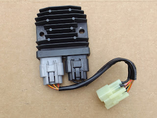
Some of the parts and tools can be found at http://www.cycleterminal.com/motorcycle-connectors.html
Here you can see the difference in size of the Units,
and space between the mounting holes.
So a few modifications to the area in which is is going to be mounted, and the mounting bracket itself.
First the mounting bracket had to be removed.
Items that had to be unbolted or removed, included the starter solenoid, battery, rear ignition coil, and of course the R&R.
After this, the brackets mounting bolts were removed,one bolt on each side under the side covers, and two from inside the battery tray.
The bracket comes straight down, then gets rotated 90 deg counter clockwise.
Then it can be rotated around the front side of the rear tire for removal.
At this piont the original studs that were welded in place had to be cut, drilled, then ground off.
Everything gets a mock fitting back on the bike, and marked for the new stud holes to be drilled.
A coat of primer and some flat black paint. And new studs fitted to make sure we had the proper length for the new R&R.
(these studs had low profile heads, so they would not interfere with the battery tray)
During the mock fitting, there was little room for everything, so to make sure I had plenty of clearance from the swing arm, and move the R&R up in the mounting bracket.
I had to remove part of a mounting bracket for a connector that did not apply to this model.
It may be used for the stator connector on a later year, or another model. (I used the dremel for this)
I had to remove part of a mounting bracket for a connector that did not apply to this model.
It may be used for the stator connector on a later year, or another model. (I used the dremel for this)
Here is the second mock fitting.
The mountiung bracket gets snuck back around the front of the rear tire, then rotated 90 deg clockwise up under the battery tray.
At this point I put the rear lower stud in place, then moved the bracket to its forward most position possible and inserted the front upper stud into position.
Here is a photo of the bracket installed, coil bolted on, and the new mounting stud.
The original Honda R&R takes a special hybid connector, manufactured just for Honda.
It has 2 x .312 terminals on the bottom for power and ground, and 3 x .250 terminals accross the top for the stator.
The 3 stator terminals were removed from the main harness connector, soldered, then the pin fit was checked once more before reinstalling then back in their connector.
I decided to leave these original harness connector as it was after rechecking my pin fit, and build an adaptor harness with a very hard to find and non existent male hybrid connector. (seen on the left in this photo)
This connector is going to hang so the insulation crimps got some dual wall shrink tubing for strain relief.
And again stator wiring was soldered as well.
R&R installed
new mating connector middle right.
You can see the connector with 3 yellow wires coming from the stator at the top of this photo.
I may replace the gray connector for the R&R and have it running directly to this connector, but it will leave one more hanging there as there is really no more room in this area.
still cold Idling around 950rpm's, Good result!!
Now I think I may get a gel battery.


No comments:
Post a Comment